Downhole logging tools
FMS/Sonic Tool String
Formation MicroScanner (FMS*)
Description
The Formation MicroScanner sonde (FMS) consists of four orthogonal imaging pads each containing 16 microelectrodes which are in direct contact with the borehole wall during the recording. The button current intensity is sampled every 0.1 in (2.5 mm). The tool works by emitting a focused current from the four pads into the formation. The current intensity variations are measured by the array of buttons on each of the pads.
Processing transforms the current intensity measurements, which reflect the microresistivity variations of the formation, into high resolution gray or color images of variable intensity. Black and white (darkest or lightest color) indicate low and high microresistivity, respectively. The tool also includes a General Purpose Inclinometry Cartridge (GPIT), which provides accelerometer and magnetometer data in order to allow one to define the tool position and spatial orientation of the data.
In smooth boreholes with very homogeneous bedding the depth of investigation is about 10 in (25 cm). The vertical resolution is 0.2 in (5 mm).
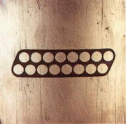
Sixteen-electrode arrangement for the four-pad tool.
Applications
- Mapping of bedding planes, fractures, faults, foliations, and other formation structures and dip determination.
- Detailed correlation of coring and logging depths.
- Precise positioning of core sections where core recovery is less than 100%.
- Analysis of depositional environments.
Log Presentation
FMS images can be plotted with identical vertical and horizontal scales to see features without exaggeration. However, due to physical constraints, different vertical and horizontal scales are commonly used. The images are displayed on an oriented plot, also called an azimuthal plot, because the images are positioned according to their orientation in the borehole with N in the center and S on both edges. Images from two passes of the tool can be merged and plotted together. The calipers or other curves can be plotted alongside the images as well.
With an additional processing step, dipmeter calculations can be made. Standard dipmeter plots consist of borehole drift, calipers, dip angle and direction (tadpoles), azimuth frequency plots, and pad traces.
Tool Specifications
| Temperature rating: | 350° F (175° C) |
| Pressure rating: | 20 kpsi (13.8 kPa) |
| Diameter: | 3.625 in (9.2 cm) |
| Length: | 25.3 ft (7.72 m) |
| Weight: | 537 lbs (243.8 Kg) |
| Sampling interval: | 0.1 in (2.5 mm) |
| Maximum logging speed | 1,800 ft/hr (549 m/hr) |
Measurement Specifications
| Vertical resolution: | 0.2 in (5 mm) |
| Depth of investigation: | 10 in (25 cm) |
* ®trademark of Schlumberger